100 m Long Thermally Drawn Supercapacitor Fibers
With Applications to 3D Printing and Textiles

Tural Khudiyev, Jung Tae Lee, Jason R. Cox, Eric Argentieri, Gabriel Loke, Rodger Yuan, Grace H. Noel, Ryoichi Tatara, Yang Yu, Frannie Logan, John Joannopoulos, Yang Shao-Horn, and Yoel Fink
Supercapacitor fibers, with short charging times, long cycle lifespans, and high power densities, hold promise for powering flexible fabric-based electronics. To date, however, only short lengths of functioning fiber supercapacitors have been produced. The primary goal of this study is to introduce a supercapacitor fiber that addresses the remaining challenges of scalability, flexibility, cladding impermeability, and performance at length. This is achieved through a top-down fabrication method in which a macroscale preform is thermally drawn into a fully functional energy-storage fiber. The preform consists of five components: thermally reversible porous electrode and electrolyte gels; conductive polymer and copper microwire current collectors; and an encapsulating hermetic cladding. This process produces 100 m of continuous functional supercapacitor fiber, orders of magnitude longer than any previously reported. In addition to flexibility (5 mm radius of curvature), moisture resistance (100 washing cycles), and strength (68 MPa), these fibers have an energy density of 306 μWh cm−2 at 3.0 V and ≈100% capacitance retention over 13 000 cycles at 1.6 V. To demonstrate the utility of this fiber, it is machine-woven and used as filament for 3D printing.
The ubiquity of mobile electronic devices and their proximity to the human body have increased interest in textile-compatible energy-storage systems.[1] Recent progress in fiber-based electronics[ 2,3] further motivates a growing need for a reliable energy-storage system that can withstand the rigors of mobile, fabric-based deployment, and preferably does not add much weight to the user.
The potential of supercapacitors as mobile energy-storage devices has long been recognized. Numerous studies have advanced the field, with recent results including high-performance active fiber materials, such as carbon nanotubes (CNT), reduced graphene oxide (rGO)/ CNT, MnO2, MXene, and conducting polymers.[4–12] The processes used to fabricate these fiber materials require multiple steps and small-scale multifilament assembly, increasing the chance of intra- and interfiber defects. As a result, the longest section of functional supercapacitor fiber reported in the literature is ≈100 cm.[8,13,14] In addition, while scalable fabrication methods have been described to prepare a single component of a supercapacitor[9,12] no single component can ultimately satisfy all of the requirements placed on the full device which requires further assembly. The practical potential of fiber-based supercapacitor devices has yet to be realized due to outstanding challenges. These include a processing approach for manufacturing at scale the entire device, as opposed to single electrode components; the ability to produce significant lengths of a fully functional storage system while retaining its performance; and finally, delivering a supercapacitor fiber that is flexible, mechanically robust, and impermeable.[15]
This study introduces the first thermally drawn supercapacitor fibers, enabled by a new thermal fiber drawing regime and a customized set of materials. Here, a five-component cell architecture is introduced that is designed to address the mechanical, environmental, electrical, and storage requirements of a textile energy-storage device. It is important to point out that when designing fibers to meet the specific practical requirements of worn textiles, significant tradeoffs exist, which have precluded their widespread deployment. For example, to deliver flexibility, robustness, and high energy density, one needs to carefully match the mechanical impedance of the cell’s individual constituents and use multiple flexible, large-area components. This, however, limits the overall storage since flexible members tend to be poor long-range conductors, and the multiplicity of interfaces creates challenges to low defect assembly at scale. Another example involves electrical connection and mechanical reliability. Short cells produced in batch processes require a high connection count and are therefore unreliable, being susceptible to contaminant (e.g., moisture) ingress, electrolyte egress, and mechanical failure. To address these complex and seemingly conflicting requirements, a flowbased preform-to-fiber (top-down) thermal drawing process[3,16] is used in which a preform of macroscale dimensions, assembled with all the five component materials, is thermally drawn into 100 m lengths of fully functional energy-storage fiber. Since the resulting 100 m fiber constitutes a single storage cell, its entire capacity can be tapped through a single electrical connection, furthering its robustness as the likelihood of failure increases with the number of vulnerabilities. While use in fabrics was an important motivation for supercapacitor fibers, this form factor is relevant for other applications such as a filament for 3D printing, allowing energy storage for 3D printed structural media.
The supercapacitor fiber materials selection criteria are defined by the constraints of the fabrication process and usage requirements. Specifically, we employ a top-down method that involves assembling a macroscopic preform, which is subsequently thermally drawn into fiber. Fabrication approaches that involve the packing of a gel electrolyte and a solid electrode[ 8,13] may result in defects that are concentrated at the gel/ electrode interface. The fluid-based drawing method allows for these packing defects to be eliminated in a manner resembling zone refinement. Additionally, the common composition of the gel matrix of the electrode and electrolyte further promotes strong adhesion. The use of PVDF as the primary component for both the electrode and electrolyte also lowers interfacial tension which in turn suppresses fluid instabilities, which can lead to interfacial defects and mixing. The specific choices of component materials work in concert to facilitate fluid-based processing and maximize surface area, enabling high storage density per unit length as well as desirable ionic transport properties (Figure S1, Supporting Information). The copper microwires in the current collector design allow for high axial electronic conductivity. While performance over length is cited as an outstanding challenge in supercapacitor fibers,[8,13,14] these issues appear to be significantly mitigated in the structure that we introduce. Finally, the COC cladding, which encases the device from preform to fiber, effectively contains the electrolyte and provides a hermetic sealing, serving as a moisture and oxygen barrier.[17] The water-impermeable cladding prevents solvent leakage, making the fiber safe for human contact and enabling long-term stability. Unlike previous fiber studies,[1,18] no post-processing is required to ensure the fiber is operational in water and safe, and the fiber form factor is preserved.
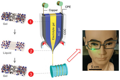
During the thermal drawing process, the preform is heated to 185 °C in a 3-zone precision furnace under constant nitrogen gas flow and scaled down by a factor of 25 into a fiber of with a cross-section of 0.96 × 0.52 mm2 (Figure 1a; Movie S1, Supporting Information). Because the preform is drawn from a viscous liquid state, a laminar flow profile is established to prevent flow instabilities and maintain the cross-sectional structure during the scaling operation.[19] To minimize flow instabilities during the draw, both the electrode and electrolyte are chosen to have similar composition. The electrode gel is prepared by combining poly(vinylidene fluoride) (PVDF), activated carbon, carbon black, and a non-aqueous electrolyte consisting of 1 m bis(trifluoromethane) sulfonimide lithium salt (LiTFSI) in propylene carbonate (PC) at 200 °C. The electrolyte gel is similarly prepared but without carbon black and activated carbon. The viscosities of these materials are reduced upon heating, and they flow at the draw temperature of 185 °C. Upon cooling to room temperature, their viscosities increase and the solid-state gels exhibit an interconnected pore structure formed via thermally induced phase separation (TIPS) (Figure S2, Supporting Information). The electric double-layer capacitor (EDLC) behavior of this gel-based capacitor architecture was verified in a coin cell (Figure S3, Supporting Information). The results demonstrate EDLC behavior that is analogous to conventional carbon-based supercapacitors.[20]
After thermal drawing, the axial and transverse architecture of the fibers are confirmed via optical microscopy (inset of Figure 1). Black activated carbon (AC) gels are separated by the transparent electrolyte gel along the fiber length, as designed at the preform level. This segregation is maintained over a length scale of a hundred meters, showcasing the scalable microstructural control of the preform-to-fiber thermal drawing process. The challenge of preventing the three fluids from mixing during the draw is met by identifying a pair of electrode and electrolyte gel materials that share a common matrix (PVDF) that minimizes the surface force imbalance between them. At the draw temperature, the viscosities of these gels are decreased, and they thin out under a highly laminar flow regime, exposing new pristine surfaces and creating an interconnected porous medium that facilitates ionic transport. In this new multi-gel drawing regime, the viscosity of gels is matched (μelectrolyte ≈ μelectrode) during the preform to fiber transition (Figure 1b). The design of the gel materials enables not only thermal drawing compatibility but also satisfactory supercapacitor performance (Figure S4, Supporting Information). If the solvent fraction in the electrolyte gel is too high, the viscosity becomes low, and the two AC electrodes separated by electrolyte gel will mix during the draw (Figure S4, Supporting Information, “mixing regime”). If the solvent fraction in the electrolyte gel is too low, with the goal of preventing mixing, the ion transport becomes limited and polarization becomes significantly high (Figure S5, Supporting Information). In the extreme case, the voltage directly jumps to the upper voltage limit when the current is applied (Figure S4, Supporting Information, “inactive regime”). Only in the “functional regime” do all three gels co-draw without mixing and demonstrate proper charge–discharge profiles. Scanning electron microscopy (SEM) of the whole fiber structure and microstructure of the porous dried supercapacitor gel components (Figure 1c) shows that the AC electrode gels are physically separated while they are in contact with the electrolyte. A 100 m long functional supercapacitor device fiber was successfully drawn (Figure 1d), validating both the scalability of the thermal drawing process and the identification of the functional regime. The design of the electrode gel should incorporate the ratio of AC-PVDF-CB that yields maximal performance. The composition of AC, CB, and PVDF determines the stored energy, electrical conductivity, and flowability. 10% of CB is close to the percolation threshold for electronic conduction. The ratio between AC and PVDF was determined by considering that AC particles increase energystorage capability and PVDF improves flowability since it melts during the draw. With low concentrations of PVDF, we observe particle aggregation and fiber breakage. Sufficiently high concentrations of PVDF improve porosity and enable the fabrication of thick electrodes. After iterating we found the optimal mass ratio to be 45–45–10 for the AC-PVDF-CB composition. At this composition, the electrode gel viscosity matches with that of the electrolyte for segregated domains and the supercapacitor exhibits one of the highest performances. However, this system is not fully optimized, and significant improvements can be made via further fine-tuning the electrode and electrolyte gels.

Figure 1. Materials and design of thermally drawn supercapacitor fibers: a) schematic diagram of supercapacitor fiber drawing process. Insets are optical microscopy images in cross-section and side view showing clear segregations between two AC electrodes. b) Viscosities of electrolyte and AC electrodes at 110 °C with respect to the shear rate. The 110 °C temperature of the fiber corresponds to the drawing temperature of ≈185 °C in the furnace. The viscosities of AC electrode and electrolyte are designed to match to prevent mixing. Viscosity-mismatched electrolyte induces gel mixing. c) SEM images of dried supercapacitor fiber including activated carbon (AC) gel and electrolyte gel. SEM images are acquired after dissolving cladding material in cyclohexane. d) 100 m of supercapacitor fiber on a spool. e) 3D profile of supercapacitor fiber. Scale bars are 500 μm.
In addition to the electrochemically active porous gel electrodes, the fiber architecture utilizes a composite current collector made up of a conductive polymer and metal wires. The preform contains two carbon-loaded polyethylene (CPE) sheets (Figure S6, Supporting Information). During the drawing process, tungsten or copper microwires are fed into two empty channels in the CPE, and this convergence technique results in fibers containing two or four wires that are fully embedded in the CPE layers (Figure S7, Supporting Information). Because its sufficiently high viscosity helps to maintain the structure of the fiber during the draw, CPE is selected as a current collector to enable transverse electronic transport. The highly conductive metallic microwires are incorporated to enable fast axial electron transport. The combination of metal and polymer enables a flexible supercapacitor with maintained performance over long lengths. Lastly, a cyclic olefin copolymer (COC) cladding is also incorporated around the macroscopic preform (Figure S6, Supporting Information), and during the thermal drawing process, its dimensions are reduced as it seamlessly encapsulates the supercapacitor fiber in situ (Figure 1e).

Figure 2. Electrochemical performance of thermally drawn supercapacitor fibers. a) Galvanostatic charge–discharge curves at different current densities. b) Long-term capacitance retention (CR) and Coulombic efficiency (CE) at 2 mA cm−2. c) Capacitance/energy versus length of fibers. The capacitance is based on the single electrode and the energy is based on the device. d) Nyquist plots of 2 m and 100 m supercapacitor fibers.
Figure 2a shows the galvanostatic charge–discharge (GCD) behavior of the thermally drawn supercapacitor fibers. The GCD curves are the symmetrical triangular shape in the absence of secondary redox reactions or high internal resistance. This is also confirmed with the cyclic voltammogram curves of our fibers at different scan rates (Figure S8, Supporting Information). The areal capacitance of the thermally drawn fiber is maintained from 244 to 220 mF cm^−2 as the current density is increased from 0.5 to 4 mA cm^−2, outperforming some previously reported fiber supercapacitors (Table S1, Supporting Information).[5,10,11,21] The thicknesses of AC electrodes in the thermally drawn supercapacitor fibers range from 180 to 360 μm, which are thicker than conventional flat electrodes.[22] Increasing the areal loading of active material does not guarantee higher capacitance, because as thickness increases, ion access is delayed, resulting in thickness-dependent electrochemical performance. However, interconnected pores formed via TIPS in the AC gel electrode preserve ion access to the active sites, ensuring fast ion transport kinetics[22] (Figure 1c). The capacitance of the supercapacitor fiber is retained nearly 100% over 13 000 cycles of charge–discharge at a current density of 2 mA cm^−2 (Figure 2b) and cycling voltage of 1.6 V. The initial capacitance is slightly increased likely due to the delayed access to the active sites, which is not uncommon in this field.[11,23]
The aspect ratio of fiber supercapacitors dictates the requirement of ultralong lengths (meters to kilometers) to achieve absolute energy levels comparable to conventional supercapacitors. Therefore, it is essential that performance is preserved at great lengths. The capacitance and energy of supercapacitor fibers is proportionally increased with the increase of internal 230 μm × 230 μm active electrodes’ lengths up to 100 m (Figure 2c). Some previous studies have reported scalable device preparation methods,[8,13] but the difference in electrochemical performance between long and short fiber devices has not been solved as the length-normalized capacitance of a fiber decreases as fiber length increases.[8,13,14] In our system, however, the Nyquist plots of 2 and 100 m fibers obtained by electrochemical impedance spectroscopy (Figure 2d) are almost identical; corroborating the assumption, that ion/ electron transport is not limited by increasing the length of fiber. The discharge profiles of thermally drawn supercapacitors of different lengths (5, 40, 80, and 100 m) show no significant polarization change, again implying efficient ion and electron transport (Figure S9, Supporting Information). The inclusion of metal wires in our fiber system also helps to improve electron transport in the axial direction as the voltage drop becomes significant with increasing fiber length otherwise. The theoretical calculation in the fiber system[24] demonstrates the Cu wire used in this study induces a small potential drop when the supercapacitor fiber length approaches 100 m compared to fiber systems with other metal current collectors or active materials (carbon materials) (Figure S10, Supporting Information). We also want to emphasize that the excellent electrochemical performance in this unprecedented length is only possible when structural uniformity is guaranteed. We can indirectly confirm the structural uniformity over the 100 m based on the linear increase of capacitance and energy of thermally drawn supercapacitor fibers and also directly verify fiber structure via optical microscopy images of the 100 m fiber at every 10 m (Figure S11, Supporting Information).
The performance of the continuous, long energy-storage fiber motivates adopting “usable energy” as a figure of merit in fiber-shaped energy-storage devices. Compared to previous approaches, the thermally drawn supercapacitor fiber has the highest total energy (Figure 3a).[4,5,12,13,25] The fiber’s hermetic cladding allows for the use of a non-aqueous electrolyte that can operate at a higher voltage (i.e., 3 V), enhancing its performance. Indeed, the areal energy of the fiber significantly increases from 43 μWh cm−2 for the 180 μm × 180 μm electrodes at 1.6 V to 306 μWh cm−2 for the 360 μm × 360 μm electrodes at 3.0 V, both at 0.5 mA cm−2 (Figure S12, Supporting Information). Furthermore, the interconnected porosity of the electrolyte and electrode in the all-gel approach enables our fiber to outperform many previously reported carbon-based supercapacitor fibers, as shown in a Ragone plot (Figure S13, Supporting Information).[5,10,11,21]

Figure 3. Comparisons with previously reported studies. a) Usable energy and areal energy density of thermally drawn supercapacitor fibers compared with fiber cells reported in prior art. The red triangle point is obtained from the supercapacitor fiber device made of two 230 μm × 230 μm AC electrodes (Fiber 2) with 1.6 V cut-off. The red diamond point is obtained from the supercapacitor fiber device made of two 360 μm × 360 μm AC electrodes (Fiber 3) with 3.0 V cut-off. b) Cycle number, cycling voltage, and capacitance retention comparison of fiber shape supercapacitors.
Intrinsic material properties that dictate higher energy and power performance should be distinguished from the extrinsic capabilities (e.g., hermetic cladding, well-bonded interfaces, etc.) provided by fiber design itself. For example, pseudocapacitors are known to exhibit higher energy performance than EDLCs.[26] This study illustrates that the extrinsic fiber properties lead to high usable energy and that the fiber fabrication process is compatible with different materials (e.g., AC, MWCNT). For instance, the thermal drawing process enables modular tuning of fiber dimensions and energy simply by adjusting the draw conditions in real-time (Figure S14, Supporting Information), regardless of its intrinsic properties. We perform experiments to investigate the dimensional effects on the performance of the supercapacitor fibers. The areal capacitance of the thermally drawn supercapacitor fiber increases to ≈490 mF cm−2 from ≈244 mF cm−2, and the length normalized capacitance increases to 17.6 from 4.4 mF cm−1 at 0.5 mA cm−2 by changing active electrode dimensions from 180 μm × 180 μm to 360 μm × 360 μm (Figure S15, Supporting Information). The length normalized capacitance is proportional to the volume or cross-sectional area (4× change in volume) and the areal capacitance is proportional to the thickness (2× change in thickness). The gravimetric and volumetric capacitances based on the 360 μm × 360 μm electrode are 43.4 F g−1 and 13.6 F cm−3, respectively. It is worth mentioning that while the porous nature of the current thermally drawn supercapacitor fiber electrodes is advantageous for ionic transport especially in thick electrodes, the larger pore volume, which is eventually dead volume in the cell compared to conventional electrodes, leads to sacrificing volumetric performance. Therefore, further studies shall be focused on fine-tuning the pore size and pore size distribution in the electrode to maximize the volumetric performance. Also, in addition to the AC-based electrodes, we successfully prepared a thermally drawn MWCNT-based supercapacitor fiber and demonstrate nearly 100% capacitance retention over 20 000 cycles (Figure S16, Supporting Information). This paves the way for the integration of other high-performance supercapacitor materials into this platform, which remains for future work.
Cycling capability is an important electrochemical performance parameter in fiber supercapacitor devices, but it is generally hindered by either low cycling number or low cycling voltage. This limitation arises in most cases where the supercapacitor fabrication does not provide hermetic encapsulation.[ 13,27] In contrast, the thermally drawn hermetic cladding allows for a non-aqueous electrolyte system that shows electrochemical stability at higher operating voltages[4,5,7,10,11,28] (Figure 3b). The mass spectroscopy (MS) studies directly show that the solvent (propylene carbonate) in the fiber does not easily diffuse out and conversely the moisture in the air does not easily diffuse in through the cladding (Figure S17, Supporting Information).
Thermally drawn supercapacitor fibers with judicious material selection and highly customized design open the door for energy-storage fabrics and structural power solutions through machine weaving and even 3D printing techniques. Thus, supercapacitor fibers must meet requirements dictated by machine weaving, 3D printing, and the various applications of the resulting objects. Therefore, the fibers should be waterresistant and mechanically robust. These requirements should be met, in addition to the energy requirements of the application, without any sacrifice of the aesthetic and tactile properties that are expected of fabrics or 3D printed objects. Indeed, our supercapacitor fibers are fully functional after machine weaving, operating during water submersion (1 month without interruption), machine washing (100 machine washing cycles), and repeated bending at a 5 mm radius of curvature (1000 bending cycles) (Figure 4a; Figures S18 and S19, and Movie S2, Supporting Information).
The textile is fully functional during repetitive deformation (Figure S20, Movie S3, Supporting Information), and the electrical conductivity of the metal wire embedded in the supercapacitor remains largely unchanged under repeated bending, twisting, and pulling (Figure S21, Supporting Information). According to COMSOL simulation results, the top-down fabrication method with a soft electrolyte at the core of the fiber enables up to two orders of magnitude lower stress than bottomup approaches of in-parallel, twisted, and co-axial designs (Figure S22, Supporting Information). The tensile strength of the thermally drawn supercapacitor is ≈68 MPa with a failure strain of ≈78.5% (Figure S23, Supporting Information). All of these capabilities, which are necessary for performance preservation and daily use, are achieved through the customized fiber design and protective COC cladding that encapsulates the whole device during the single-step thermal drawing process.

Figure 4. Fabric and 3D printed composite objects made with supercapacitor fibers: a) capacitance retention of thermally drawn supercapacitor fibers in harsh conditions; fibers are fully functional in harsh conditions such as repetitive mechanical bending (1000 cycles with a bending radius of 5 mm), 100 machine washing cycles, post-machine weaving, and underwater charge–discharge for 1 month continuously, b) charge–discharge curves of fibers connected in series and parallel; these fibers can also be connected in series or parallel to have desired capacitances and voltages, c) schematic diagram of machine-weaving and 3D printing from thermally drawn supercapacitor fiber; These fibers can be directly machine woven or crocheted (i.e. bracelet) into large scale textiles and further integrated with other fiber based devices in textile. 100 × 15.2 cm2 multifunctional textile containing twelve 1 m supercapacitors (4S3P) and a 3 m light emitting fiber with 20 discrete light emitting diodes is demonstrated. The thermally drawn supercapacitor fiber can also be used as a print filament of 3D printing. The drawn fiber on a spool is directly transferred to a printer nozzle and printed into a supercapacitor eyeglasses frame for custom structural power solutions.
Fibers can be combined either in series or in parallel, allowing engineers to craft custom, flexible power solutions. The incremental voltage increases by connecting multiple fibers in series, and the capacitance increases by connecting fibers in parallel as shown in Figure 4b. We successfully prepared a fully machine-woven 100 cm × 100 cm supercapacitor textile (Figure 4c and Movies S4,S5, Supporting Information) and two 15.2 cm × 100 cm textiles employing supercapacitor fibers and a light-emitting fiber (Figure 4c; Movies S6,S7, Supporting Information). The latter contains twenty discrete green light-emitting diodes in a single fiber powered by twelve 100 cm supercapacitor fibers (4S3P configuration). We also show a manually woven bracelet in Figure 4c made of 100% thermally drawn supercapacitor fiber. We incorporated a secondary elastomeric COC (eCOC) cladding around the COC-clad functional supercapacitor preform, and drew this preform into a hundred meters long in a single process. The function of eCOC is to provide elasticity and extreme bendability (radius of curvature ≈1 mm).
The ability to simply modify the architecture of supercapacitor fibers offers new opportunities for utilization in different processes. As an example, we demonstrate 3D printing of supercapacitor fibers into custom-shaped energy solutions. Printing of supercapacitor devices is challenging because the different materials making up the electrodes, electrolytes, and insulators are not printable; the device may degrade upon exposure to heat or air; and a small radius of curvature (1 mm) could damage the device. To overcome these challenges, we incorporated a secondary polycaprolactone (PCL) cladding around the COC-clad supercapacitor preform and drew this preform into a 100 m long, 3D-printable fiber. PCL is selected as the outer cladding because it has a low melting temperature of 60 °C compared to the internal sub-cladding COC which starts to soften at 80 °C. Thus, during printing, PCL is able to lower its viscosity and fuse to adjacent print lines, while the internal COC remains at its solid state so as to protect the supercapacitor device domain from any structural deformation which could result in the printed line to lose its function. This optimal cladding material combination and the long lengths of our supercapacitor fibers enable their use as a print filament feedstock (see Experimental Section). We then printed our fibers into a custom-designed supercapacitor-based eyeglasses frame (Figure 4c; Movies S8 and S9, Supporting Information) with energy-storage capability structurally encapsulated across 100% of the frame’s volume. The resolution of the supercapacitor printing is dependent on the diameter of fiber that is being printed since the size of the nozzle hole is the same as the fiber diameter. In our experiments, we have printed fibers of diameters down to 0.8 mm. As such, the minimum print resolution achieved in this work is 0.8 mm.
The ability to scale the thermally drawn supercapacitor fibers further allows for the powering of more advanced electronic systems, such as a microcontroller and diode system. The ability to simultaneously power a microcontroller and LED enables digital transmission for free space optical data communication. As a proof of concept, data transmission using in-fiber LEDs has been demonstrated. The microcontroller (MCU), supercapacitor fiber, and light emitting fiber are woven into a skirt and the information is digitalized through an optical signal. A smartphone app that allows a user to capture the LED emission with a camera interprets the digital code and presents a unique user avatar on the screen (Figure S24a and Movies S10,S11, Supporting Information). Our current supercapacitor fibers can also power a wide range of electronic components such as sensors, microphones, switches, etc. (Figure S24a,b, Supporting Information).
A five-component cell architecture that addresses the mechanical, environmental, electrical, and energy-storage requirements of a textile energy-storage devices is introduced. The flow-based, preform-to-fiber (top-down) thermal drawing process is used to scale down the cross-section of a macroscopic preform 25× to produce 100-m lengths of a fully functional energy-storage fiber. The laminar viscous flow of the draw process preserves the cross-section architecture during the preform-to-fiber transition. This flow is achieved by an allgel electrode–electrolyte system that also enables high ionic conductivity across the cell interfaces. A higher modulus current collector around the soft, core gel materials consists of a large surface-area conductive polymer and metal microwires to deliver flexibility, robustness, and high axial conductivity with no loss in cell performance up to 100 m. We achieve supercapacitor fibers with maximum areal energy density of 306 μWh cm−2 and usable energy of ≈24 mWh. Lastly, in situ hermetic sealing ensures moisture resistance, enabling longterm stability over charge–discharge cycles and the employment of a non-aqueous electrolyte for high-voltage operation. Nearly 100% of the initial capacitance is retained after 13 000 cycles at 1.6 V. Thermally drawn supercapacitor fibers remain fully functional even after 3D printing, machine weaving, underwater operation, and repetitive mechanical bending. The ability to incorporate supercapacitor fiber of extended lengths and good electrochemical performance into a variety of structures including, composites, textiles, and 3D printed media has implications to a wide range of applications where electrical power is needed and added weight should be kept to a minimum.
Experimental Section
Thermally Drawable Supercapacitor Gels: The activated carbon (AC) (MTI Corporation), carbon black (VWR), PVDF (Arkema Inc.), and 1 m LiTFSI in PC were mixed at 200 °C in an argon-glovebox (<1 ppm of H2O, Innovative Technologies) for electrochemically active gels. For electrodes, one of the optimal ratios that simultaneously provided thermally flowable, sufficient porosity, high conductive, and high performance was used. The ratio of active material: carbon black: PVDF was 45:10:45 by weight. The electrolyte gel was prepared by mixing PVDF and 1 m LiTFSI in PC at 200 °C. The hot gels were poured onto the glass substrate, and flat films were produced in the glovebox.
Preform Fabrication and Fiber Drawing: Ribbon supercapacitor fibers were drawn from a macroscopic rectangular preform. The thickness, width, and the length of the preform were ≈13, ≈24, and ≈300 mm, respectively. First, conductive polyethylene (CPE) containing void channels (1 mm × 1 mm) for two copper (or tungsten) wires (40–100 μm diameter) and cycloolefin copolymer (COC) (Topas) cladding containing five void channels for two CPE, AC, and electrolyte gels were consolidated with hot-press at 125 °C. The cross-sectional dimensions for five void channels were two 1.5 mm × 9 mm for CPE, two 5 mm × 5 mm for two AC gel bars, and one 4 mm × 6 mm for an electrolyte gel bar. The preform was transferred to the Ar glovebox, and two AC gels cathode, anode, and electrolyte gels were inserted into the preform. The open end in the preform for gel insertion was sealed by polyimide tape and chemically resistant epoxy. The preform was drawn in a three-zone vertical tube furnace with a top-zone temperature of 90 °C, a middlezone temperature of 185 °C, and a bottom-zone temperature of 60 °C while feeding copper (or tungsten) wires under nitrogen flow. The fiber dimensions were monitored with laser micrometers.
Electrochemical Characterization: The long supercapacitor fiber was cut to the desired length and sealed with paraffin wax inside an Ar glovebox. These studies were performed both in centimeter and meter scale fibers in length with <1 mm width and 500 μm thickness unless it was mentioned specifically. The fiber cells were connected with Cu wire. They were cycled between 1.6 V (or 3.0 V) and 0.01 V at the different current rates (10, 20, 40, 80 μA cm−1) in galvanostatic mode via Arbin battery test system (Arbin Instruments). Cyclovoltammetry was done with a voltage window from 0.01 to 1.6V at different scan rates (5, 10, 20, 50 mV s−1). Electrochemical impedance spectroscopy (EIS) measurements were carried out using VMP3 (Bio-logic) at open circuit potential with 10 mV amplitude and frequency range from 7 MHz to 10 mHz at room temperature. In all experiments, connections that were on the same edge of the fiber were used.
Calculation Method for Electrochemical Performance: The capacitance for thermally drawn supercapacitor fiber was calculated from both cyclovoltammogram and galvanostatic charge/discharge curves. In CV curves, the capacitance was calculated by the equation of C = 1/(s*Δt)*∫I(V)dV where C is the capacitance, I is the current, s is the scan rate (Vt−1), and V is potential. In galvanostatic charge–discharge curves, the capacitance was derived from the equation of C = 2I/(ΔV/Δt) where I is the discharge current and the ΔV/Δt is the slope of the discharge curve. The areal capacitance, gravimetric capacitance, and volumetric capacitance were calculated by dividing C by area, mass, and volume of single active fiber. The energy (E = 1/8*C ΔV^2 ) and power (P = E/Δt) of supercapacitor fiber devices were calculated from galvanostatic discharge curves. The areal, gravimetric, and volumetric capacitances were obtained from single electrode and the areal energy and power were obtained from the device. The area to calculate areal performance was the projected area of active gel electrode both for fiber and coin cell.
3D Printing of Thermally Drawn Supercapacitor Fiber: The Rova3D multi-nozzle printer was used. The nozzle was custom-made with a short (≈0.3 mm) stainless steel hot end that had the same diameter as the fiber diameter. The hot end was heated by a nichrome wire. The key idea for this printing methodology was to heat up the outer surface (PCL layer) of the supercapacitor fiber for adhesion, while the internal domains within the fiber were still maintained at its solid state so that its device functionality could be retained during printing.
The supercapacitor fiber was printed at a speed of 100–110 mm min−1 at a temperature of 85–95 °C with the ratio of the depositing speed and printing translation speed kept at 1:1. It was started from a printing temperature of 70 °C, a value which was between the melting point of PCL (60 °C) and the softening temperature of COC (80 °C). For the temperature of ≈70 °C, a range of print speeds that is valid (40–80 mm min−1) was determined. At print speeds below 40 mm min−1, the structure of the device domain, as viewed by an optical microscope, was compressed and deformed with mixing of the electrode and electrolyte materials. In addition, when measuring the performance of the supercapacitor at this print setting, there was shorting between the electrodes. While at print speeds above 80 mm min−1, the outer cladding of the deposited fiber was not hot enough to adhere to print bed, evident by the peeling of the print lines off the print bed. To achieve higher print speeds above 80 mm min−1, one could use a higher print temperature. A print temperature of ≈90 °C was then tested. At this temperature, it was found that the maximum print speed was 110 mm min−1 before poor adhesion takes place. At this setting, there was also little to no noticeable change to the structural integrity of the supercapacitor domain when viewed under the optical microscope. As such, a print temperature ≈90 °C and print speed of ≈110 mm min−1 were eventually used.
A PCL layer was used at the bottom layer to increase adhesion of the first layer of the printed eyeglasses to the printing bed. The input layer height was set as the diameter of the fiber. The 3D design was done in SolidWorks and later processed in Slic3r to create a gcode file. The gcode was then read by the Pronterface Software which communicates the required XYZ print positions to the printer.
Machine Weaving: An automated weaving machine (CCi Studio 500 Premium Sampling Loom) was utilized to demonstrate the supercapacitor fabric. The base material was a plain weave construction, and the supercapacitor fiber sat in a double weave channel. This fabric was woven at 32 picks per inch in the filling direction and 50 ends per inch in the warp direction. In these fabrics, the warp material was 20/2 mercerized cotton and the weft material (other than supercapacitor fiber) was 600 denier polyester. The machine-woven supercapacitor fibers were connected in series and parallel from the extended section of fiber.
Machine Washing: The supercapacitor fibers were placed in the protective delicate laundry bag and washed with a portable mini washing machine (PYLE PUCWM11). The supercapacitor fibers experienced 100 washing cycles and each cycle was 15 min (“cotton” wash mode) at temperature of 45 °C. No detergent was used during machine washing.
Mechanical Test: The test was performed in a universal testing machine Instron 5967. The tests were carried out on specimens with 50-cm gauge length and 1-m fiber length using the displacement control at a rate of 0.5 mm min−1. The cross-section area of the supercapacitor fiber device was ≈0.5 mm2 (0.53 mm × 0.95 mm). Young’s modulus for tested supercapacitor fiber was 2556 MPa and tensile stress at yield was 68 MPa.
Mass Spectroscopy: The mass spectrometry setup was made in-house for detection of the gas evolution in the head space of the cell along with pressure monitoring. The cell volume was around 6 cm3 for the measurement and Argon (Airgas, 99.999% pure, O2, H2O, CO2 < 1ppm) was used as a carrier gas. The MS cells for fiber with electrolyte gel were prepared inside an argon-filled glovebox (<0.5 ppm of H2O and O2), and the MS cell for the COC-enclosed water and pure water was assembled outside the glovebox and evacuate and pressurized with Argon three times prior to measurement to ensure minimum contamination from the ambient air. MS measurement was started 4 h after pressurization with a time interval of 30 min to collect the gas evolved from the headspace to obtain a CO2 (m/z = 44) evolution or H2O (m/z = 18) evolution coming from PC and water evaporation, respectively. The MS cell temperature was controlled with an environmental chamber (Espec BTZ-133).
Supporting Information
Supporting Information is available from the Wiley Online Library or from the author.
Acknowledgements
This work was supported by the MIT MRSEC through the MRSEC Program of the National Science Foundation under award number DMR-1419807, the US Army Research Laboratory and the US Army Research Office through the Institute for Soldier Nanotechnologies under contract number W911NF-13-D-000, and the National Science Foundation Graduate Research Fellowship under Grant No. 174530. J.T.L. gratefully acknowledges support from NRF-2020R1C1C1003656. The poly(vinylidenefluoride) powders were generously supplied by Arkema Inc.
Conflict of Interest
The authors declare no conflict of interest.
Author Contributions
T.K. and J.T.L. contributed equally to this work. T.K., J.T.L., and Y.F. conceived of the idea toward supercapacitor fibers, fabrics, and 3D printed systems. T.K. and J.T.L. designed and implemented the experiments toward the drawing of the supercapacitor fibers. T.K. and J.T.L. contributed to the electrochemical and material characterization of the fibers. J.C. developed supercapacitor-powered data communication system and fabric. E.A. performed rheometer measurements. T.K. and G.L. designed and implemented experiments toward the 3D printing of supercapacitor fibers. R.Y. performed COMSOL simulations. G.H.N. provided critical feedback and helped shape the manuscript. R.T. and T.K. performed impedance measurements. Y.Y. performed mass spectroscopy experiments. F.L. conceived, designed, and machine-weaved the textiles integrating the supercapacitor fibers. J.J. contributed to the ideas that optimize the thermal drawing experiments and applications of these supercapacitor fibers. Y.S.H. gave feedback and contributed ideas to the electrochemical performance and applications of these supercapacitor fibers. T.K., J.T.L., and Y.F. wrote the paper with input from all authors. Y.F. supervised the project.
Keywords
3D printing, energy-storage textiles, machine weaving, multimaterial thermal drawing, porous electrodes, supercapacitor fibers, thermally reversible gels.